This entry is for people who use the LaTeX document preparation system, as I did in the book. It’s not a tutorial on LaTeX in general, but shows some techniques for drawing quantum circuits. To be direct, it’s pretty geeky for LaTeX people.
An early decision I had to make was how to draw quantum circuit diagrams in the book. Here’s an example of one:
This includes three Hadamard H gates, two S gates, a T gate, and a swap gate. Would I need to write my own drawing routines?
I really didn’t want to do that because of my time constraints but I also hoped that I could find something better. It didn’t take me long to do so: Alastair Kay’s excellent quantikx package on the CTAN Comprehensive TeX Archive Network. The documentation there is very good, but in this blog entry I’m going to show you how to evolve a simple circuit to have stylistic customizations that you might want to modify and use.
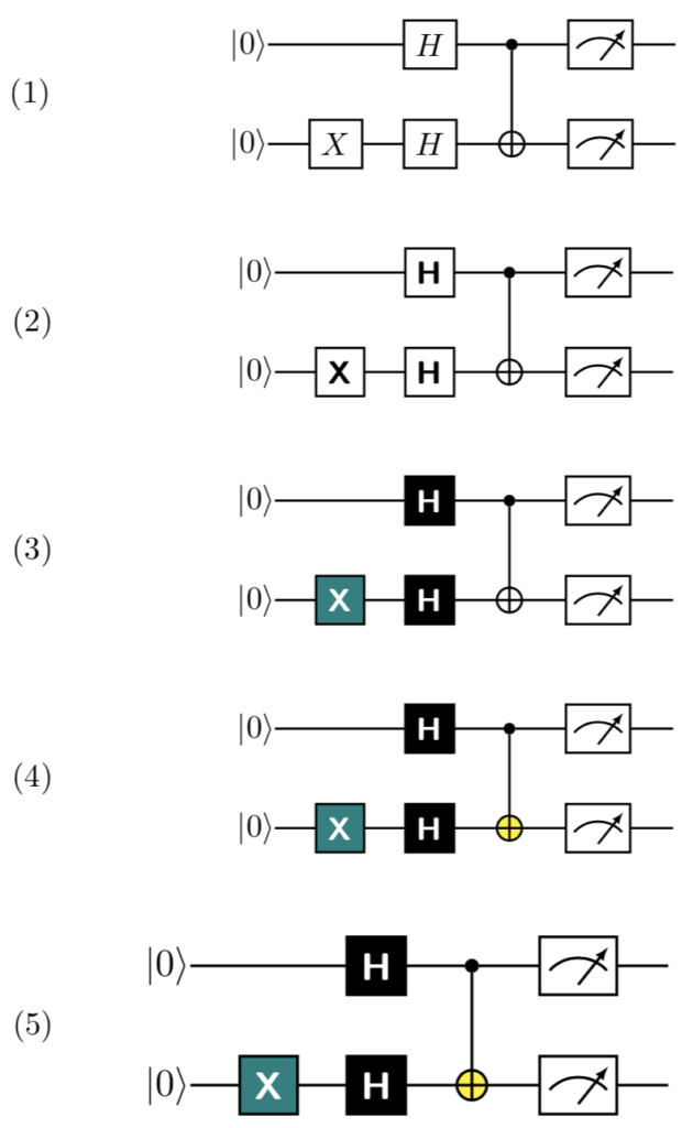
Below are five displayed versions of the same circuit. They are numbered on the left side.
The first is the default formatting from quantikz. It is perfectly fine and you can see similarly formatted circuits in research articles about quantum computing.
\begin{center}
    \begin{tikzpicture}
        \node[scale=1.0] {
            \begin{quantikz}
                \ket{0} & \qw       & \gate{H} & \ctrl{1}   & \meter{} & \qw \\
                \ket{0} & \gate{X}  & \gate{H} & \targ{}    & \meter{} & \qw
            \end{quantikz}
        };
    \end{tikzpicture}
\end{center}
The markup \ket{0} produces the |0> at the beginning of each wire, which is a horizontal line. \qw creates a segment of a quantum wire. \gate is the basic command for drawing a labeled gate with a rectangle. \meter is the quantum measurement operator. \ctrl{1} and \targ{} are the two parts of a CNOT two-qubit gate. \ctrl{1} is on the wire for the control qubit and extends a line down one wire. There the line meets the \targ{} (target) qubit and is drawn as a circle around a “+” sign.
In the second example, I’ve changed the font in the H and X gates.
\newcommand*{\gateStyle}[1]{{\textsf{\bfseries #1}}}
\newcommand*{\hGate}{\gateStyle{H}}
\newcommand*{\xGate}{\gateStyle{X}}

\begin{center}
    \begin{tikzpicture}
        \node[scale=1.0] {
            \begin{quantikz}
                \ket{0} & \qw            & \gate{\hGate} & \ctrl{1}   & \meter{} & \qw \\
                \ket{0} & \gate{\xGate}  & \gate{\hGate} & \targ{}    & \meter{} & \qw
            \end{quantikz}
        };
    \end{tikzpicture}
\end{center}
I added three LaTeX macros to encapsulate the new function and make it easier to reuse.
\gatestyleputs its text in a bold sans serif font.\hGatedraws the Hadamard H using\gatestyle.\xGatedraws the X using\gatestyle.
While it is now easier to use \hGate and \xGate for text, it’s still wordy to use them as gates in a circuit. The third example defines two more macros, \circuitH and \circuitX, and shows how to set the background and font colors. For a printed book, you might want to have gates with backgrounds in different shades of gray. Alternatively, you could use the same background color for all the Clifford gates.
\newcommand*{\circuitH}{\gate[style={fill=black},label style=white]{\textnormal{\hGate{}}}}
\newcommand*{\circuitX}{\gate[style={fill=teal},label style=white]{\textnormal{\xGate}}}

\begin{center}
    \begin{tikzpicture}
        \node[scale=1.0] {
            \begin{quantikz}
                \ket{0} & \qw            & \circuitH & \ctrl{1}   & \meter{} & \qw \\
                \ket{0} & \circuitX      & \circuitH & \targ{}    & \meter{} & \qw
            \end{quantikz}
        };
    \end{tikzpicture}
\end{center}
Now let’s set the color for the circle in \targ.
\newcommand*{\circuitTarget}[1]{\targ[style={fill=yellow}]{#1}}

\begin{center}
    \begin{tikzpicture}
        \node[scale=1.0] {
            \begin{quantikz}
                \ket{0} & \qw            & \circuitH & \ctrl{1}         & \meter{} & \qw \\
                \ket{0} & \circuitX      & \circuitH & \circuitTarget{} & \meter{} & \qw
            \end{quantikz}
        };
    \end{tikzpicture}
\end{center}
I think you get the idea. You can also set the background color for \meter, which I leave to you as an exercise. Note that in the April, 2019, version of quantikx, you could not change the color of the line inside the \meter graphic. You need to copy and redefine the macro (or create a new macro) to do that.
Finally, let me explain what that [scale=1.0] is doing after the \node. This allows you to scale the entire drawing and make it larger or smaller. However, it does not change the text size. The fifth example shows the fourth example drawn 20% larger.
\begin{center}
    \begin{tikzpicture}
        \node[scale=1.2] {
            \begin{quantikz}
                \ket{0} & \qw            & \circuitH & \ctrl{1}         & \meter{} & \qw \\
                \ket{0} & \circuitX      & \circuitH & \circuitTarget{} & \meter{} & \qw
            \end{quantikz}
        };
    \end{tikzpicture}
\end{center}
Here is the complete LaTeX file I used to generate the examples:
\usetikzlibrary{quantikz}

\mainmatter


\begin{center}
    \begin{tikzpicture}
        \node at (-5,0) {(1)};
        \node[scale=1.0] {
            \begin{quantikz}
                \ket{0} & \qw       & \gate{H} & \ctrl{1}   & \meter{} & \qw \\
                \ket{0} & \gate{X}  & \gate{H} & \targ{}    & \meter{} & \qw
            \end{quantikz}
        };
    \end{tikzpicture}
\end{center}


\newcommand*{\gateStyle}[1]{{\textsf{\bfseries #1}}}
\newcommand*{\hGate}{\gateStyle{H}}
\newcommand*{\xGate}{\gateStyle{X}}

\begin{center}
    \begin{tikzpicture}
        \node at (-5,0) {(2)};
        \node[scale=1.0] {
            \begin{quantikz}
                \ket{0} & \qw            & \gate{\hGate} & \ctrl{1}   & \meter{} & \qw \\
                \ket{0} & \gate{\xGate}  & \gate{\hGate} & \targ{}    & \meter{} & \qw
            \end{quantikz}
        };
    \end{tikzpicture}
\end{center}


\newcommand*{\circuitH}{\gate[style={fill=black},label style=white]{\textnormal{\hGate{}}}}
\newcommand*{\circuitX}{\gate[style={fill=teal},label style=white]{\textnormal{\xGate}}}

\begin{center}
    \begin{tikzpicture}
        \node at (-5,0) {(3)};
        \node[scale=1.0] {
            \begin{quantikz}
                \ket{0} & \qw            & \circuitH & \ctrl{1}   & \meter{} & \qw \\
                \ket{0} & \circuitX      & \circuitH & \targ{}    & \meter{} & \qw
            \end{quantikz}
        };
    \end{tikzpicture}
\end{center}


\newcommand*{\circuitTarget}[1]{\targ[style={fill=yellow}]{#1}}

\begin{center}
    \begin{tikzpicture}
        \node at (-5,0) {(4)};
        \node[scale=1.0] {
            \begin{quantikz}
                \ket{0} & \qw            & \circuitH & \ctrl{1}         & \meter{} & \qw \\
                \ket{0} & \circuitX      & \circuitH & \circuitTarget{} & \meter{} & \qw
            \end{quantikz}
        };
    \end{tikzpicture}
\end{center}


\begin{center}
    \begin{tikzpicture}
        \node at (-4.4,0) {(5)};
        \node[scale=1.2] {
            \begin{quantikz}
                \ket{0} & \qw            & \circuitH & \ctrl{1}         & \meter{} & \qw \\
                \ket{0} & \circuitX      & \circuitH & \circuitTarget{} & \meter{} & \qw
            \end{quantikz}
        };
    \end{tikzpicture}
\end{center}
Previous: My five rules for making revisions from editorial comments
Next: What’s in the book
| In December, 2019, Packt Publishing published my book Dancing with Qubits: How quantum computing works and how it can change the world. Through a series of blog entries, I talk about the writing and publishing process, and then about the content. |


